


Next: Subarray readouts (windowed images)
Up: Camera Readout Options
Previous: Camera Readout Options
Contents
Layout of the FITS Images: Image and Overscan Sections
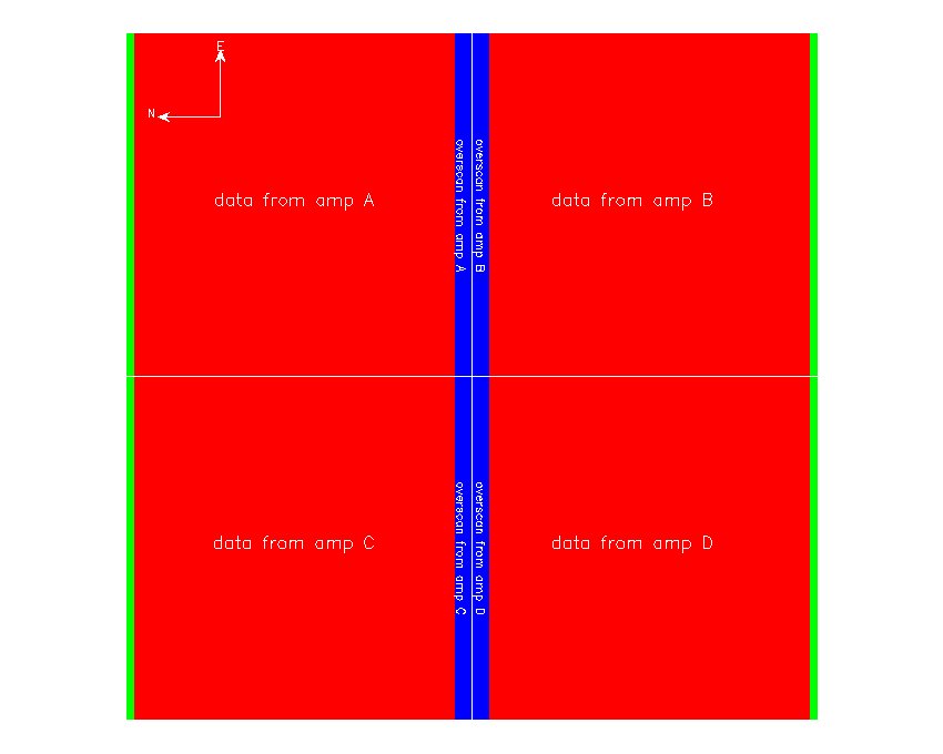
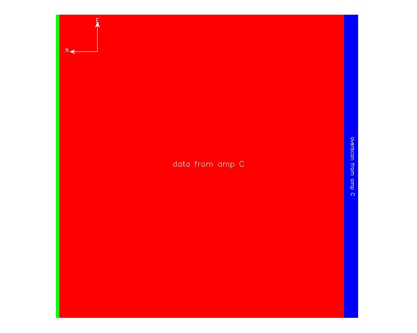
Each FITS image consists of both image and overscan pixels. The image pixels may actually be binned pixels. In addition to overscan regions, there are other "excess" (bias-level) pixels along the outer edges of each image. In any case, the overscan regions appear on the opposite side of the area of the CCD readout by each amplifier. This means that for readouts through amplifier C only, the overscan region appears as a strip running in the column direction on the righthand side of the images. For readouts through ALL four amplifiers, there are four readout strips that together bisect the center of the image.
The following figures illustrate the location of the image pixels readout through the different amplifiers and the overscan and excess pixels:
Figure 3.6:
Location of the image pixel readout through all the different amplifiers and the overscan and excess pixels
.
|
Figure 3.7:
Location of the image pixel readout through the C amplifier and the overscan and excess pixels
.
|
Keywords in the image headers describe the exact configuration of the RCT images. See Section ![[*]](file:/sw/share/lib/latex2html/icons/crossref.png) .
.
Next: Subarray readouts (windowed images)
Up: Camera Readout Options
Previous: Camera Readout Options
Contents
Louis-Gregory Strolger
2012-01-09